I really liked the look of some Fluke Digital Multimeters I'd seen at work, they're so colourful:
I thought it'd be fun to try to re-purpose one as a clock -- replace the original LCD with a small LCD clock.
I went to eBay, didn't have any luck finding the Fluke model, but did find this (inoperative) "Simpson 467" for less than $10:
Still nicely colourful, but quite a bit smaller than the Fluke. I disassembled it and cleared out some space in the interior, beween the upper and lower circuit boards.
I removed the original LCD and wired up a couple of the switches on the front panel. I got a cheap LCD alarm clock and disassembled that.
I soldered the leads from the DMM switches to the clock's switch contacts and started experimenting with a ribbon cable to run from the clock circuit board inside the DMM housing out to the LCD in front:
However it really wasn't working out, the LCD was much too fiddly and I couldn't see an acceptable way to mount it where the original LCD sat. So I put the bits away in a box and there they gathered dust for a long time. But then I saw an advertisement for the LEDkit clock. I realised that it offered the flexibility I was looking for, and I could not imagine anything with a smaller clock circuit board.
I ordered the red kit and when it arrived I started work. Because I had so little space, I halved the number of LEDs, I use one for each segment, rather than two. Note that halving the number of LEDs only works with the red LED kit, not the blue one.
I drilled a jig for the LEDs, placing them much closer together than large panel that comes with the kit. So close in fact that I connected some LEDs by soldered their leads together.
I also carefully soldered small wires onto the clock board to "bridge" the button so I could set the time using the DMM's front panel button.
My first digit group worked so I made the rest. I drilled a more careful panel to hold the LEDs and added additional parts to seat the whole thing between the DMM circuit boards.
I wrote some PostScript to draw a cutting guide which I glued onto aluminium foil.
Once cut, this provided tiny "windows" in the opaque foil for the LEDs to glow through.
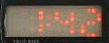
Time to put it all together. A bit of a squeeze, but it all fit and worked! The red power button at top right turns the clock off and on, the button to it's immediate left ("Peak Hold") is the "Set" button.
The legend includes a shout-out to LEDkit.biz, I couldn't've completed the project without it!
You can see more photos (and larger) in my flickr set.


")


 + 4.5V 700mA 60Hz")
")